Networks form the arteries of many modern show control systems, pumping information around all the various parts, keeping everything connected to the flow of information. Understanding the general layout of networks is important for making decision later, and understanding why certain choices have been made. In this post, we will talk about some of the more common topologies, including:
- Ring
- Star
- Mesh
- Line
Terminology
To understand networks, it’s important to cover some basic terminology first.
Node

A node in networking is one of two things, an endpoint, or a distribution point. For example, every computer on a network is an endpoint. This is where the information is being sent to or from. A distribution point may be your switch that sits between the two. It connects the two endpoints and distributes the messages between them. This is what allows large networked systems to function as the distribution nodes can route information around the network without all of the endpoints knowing the exact structure of the network.
Link
A link in a network is the physical connection between two nodes. This is specifically the physical media, not the protocol that we are thinking about.
For example, Ethernet and WiFi would be thought of as Cable and Radio Waves respectively.
Without links, the network is completely disconnected. No two nodes can communicate with each other as they have no link, however it is important to understand that nodes don’t always require a direct link between devices (In fact, most devices aren’t directly connected) to be able to communicate. Think of your network at home, your computer has a link to your router, which has its own link to your internet provider. Your computer uses routers link to access the internet.

Point to Point
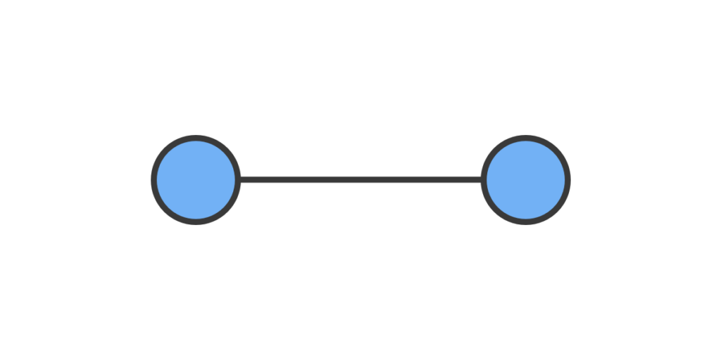
The simplest form of network, a point to point network connects two nodes with a link. This may be a dedicated link, or it may be dynamically created as required. For example, two tins with a string between have a dedicated link. The link remains even when not in use. Alternatively, the link may be negotiated and created as a direct point-to-point link which only exists whilst it’s in use. An example of this would be old phone systems where you would negotiate with the operator who would then make the direct connection for you.
Diasy Chain
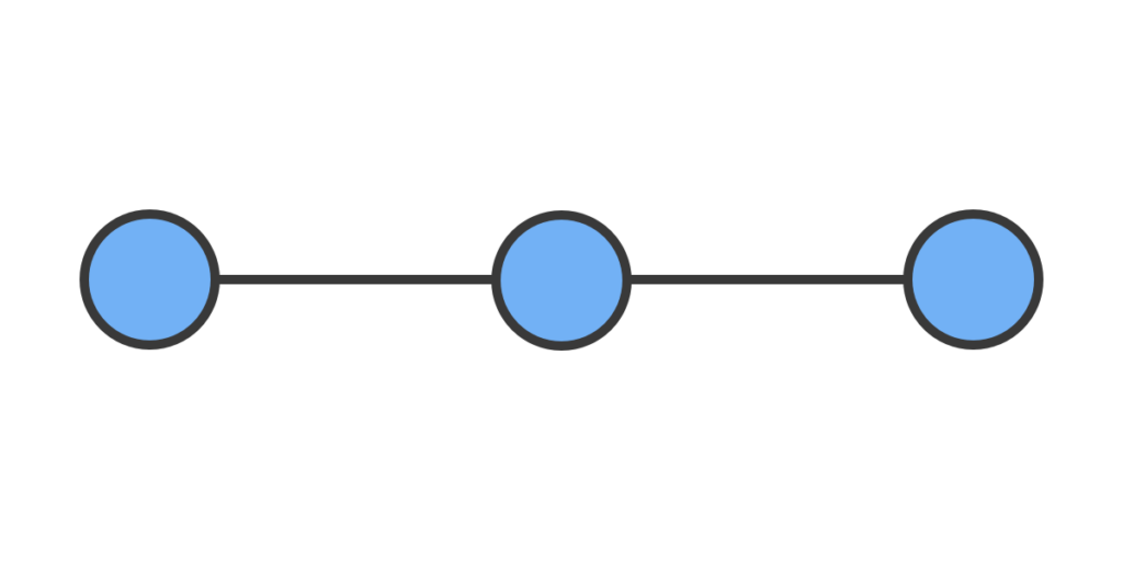
Daisy Chaining involves connecting nodes in series. If a message needs to travel to a node part way down the chain, it is passed on by all devices in the network before it, creating a sort of relay to the node that needs it.
Daisy Chain networks come in two varietys:
- Linear
- Ring
A Linear Daisy Chain is modelled like above, each device is connected to the next and last in the chain and must have both transmission and receiving links between nodes so that messages can be sent in either direction. These were expensive in the early days of networking due to the requirement for send and receive and as such weren’t massively popular.
Ring Daisy Chains solved this issue by connecting the first and last node together to create a ring (More info below). This allowed for a single link between nodes that allows data to be sent in a single direction. Data could then be sent around the ring until it reaches the node it’s destined for. It does have the drawback that data between two adjacent nodes may have to traverse the entire ring making responses take much longer in one direction.
Bus
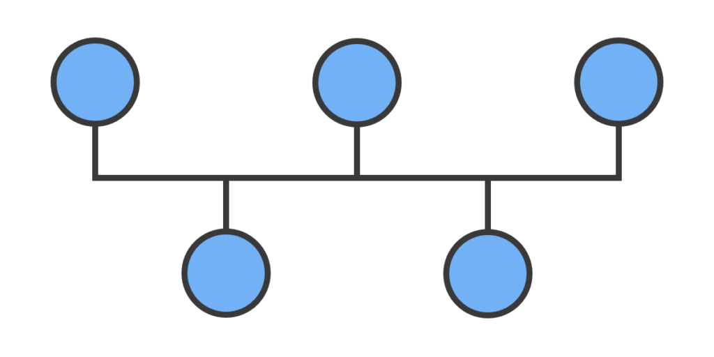
Bus topology connects all nodes to a central backbone. Data is transmitted over this backbone to all nodes on the network, and the node would check the address. If the address matched its own it would pay attention to the data otherwise it would ignore the message and continue listening. It was cheaper than alternatives as it only requires a single wire to transmit data however the management of the network often offset this. Data being transmitted can also be received by multiple nodes.
While most people use the term daisy chaining when talking about DMX, it is actually a Bus Topology. The Bus or backbone is creating by connecting cables in a daisy chain style, but electrically they are a bus with spurs off to the device in question.
Star
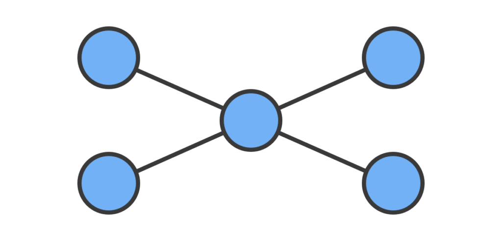
A Star topology is one of the most common network topologies today. It features a central node with others connected in a spoke fashion around the edge. The edge nodes all communicate via the central node which acts as a repeater or distributor, passing data to other edge nodes. The star topology is considered one of the easiest to work with, as adding additional device are easy to add to the network. The main disadvantage of the star topology are when considering points of failure and bandwidth. As all edge nodes connect directly to the central node, a failure of that node would result in complete failure of the network. In terms of bandwidth, as every message is traversing the central node, it has much higher bandwidth requirements to function without becoming a bottle neck to the network as a whole.
Extended Star
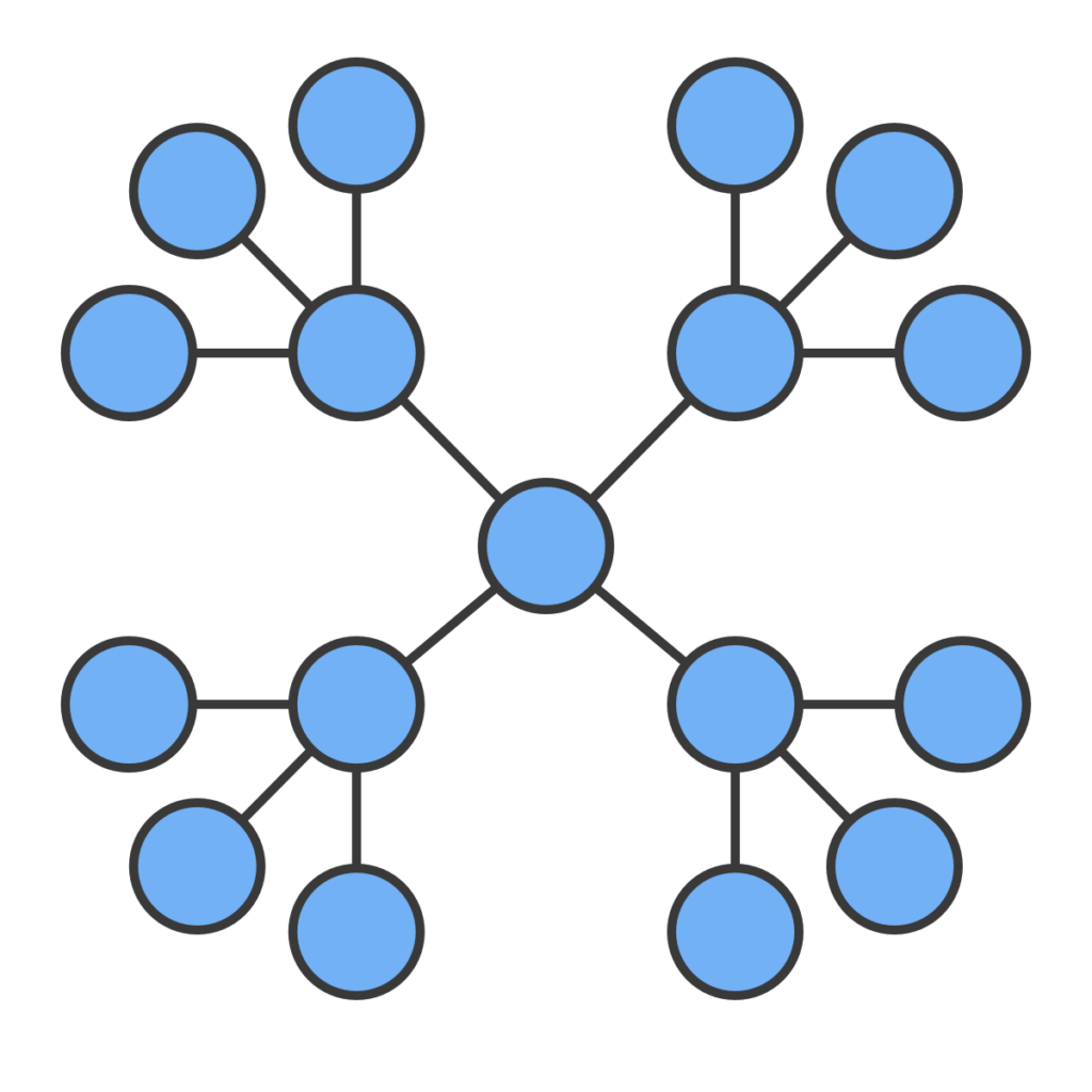
An extended star topology takes the star topology and extends it a level. This allows for further transmission distance. By using switches or hubs at the intermediary level, the extended star can alleviate some of the issues with star networks by allowing some devices to communicate via the intermediary node. This style of networks is technically a hybrid network, combining multiple star levels. It is also referred to as a “Star of Stars” network.
Ring
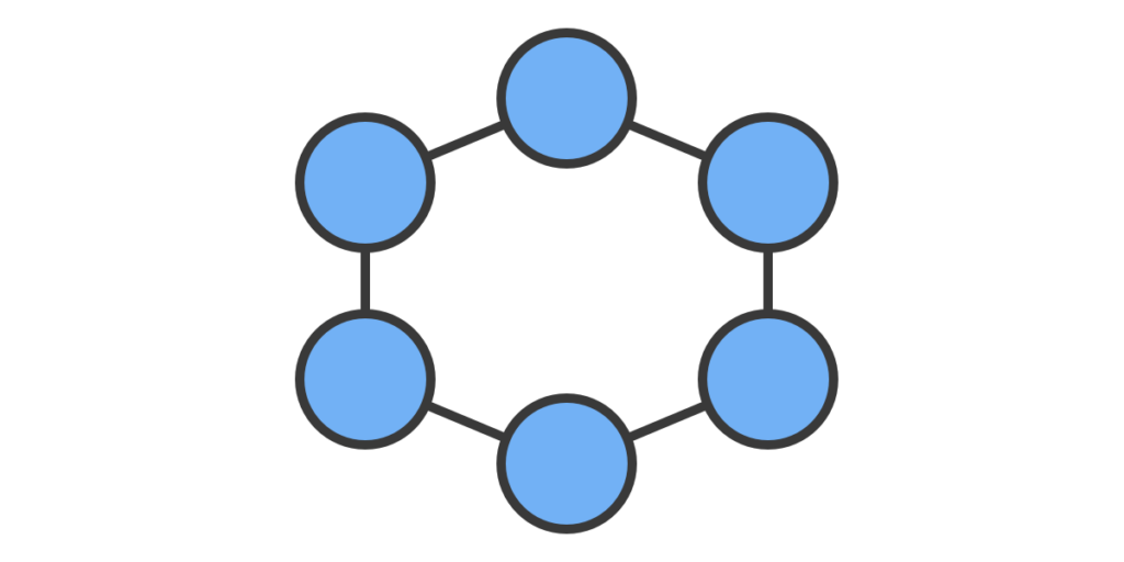
A ring network is a daisy chained network, where the first and last node are connected. This allows data to travel around the ring to get to any of the other nodes in the network. Modern ring networks allow data to travel in either direction around the network, this allows any node to fail with no loss of routes between nodes. Only if two non-adjacent nodes where lost would routes become unable to communicate. This can result in a ‘split’ network situation where we end up with two or more separate networks, and becomes an important topic when dealing with stacking nodes and devices.
Fully Connected
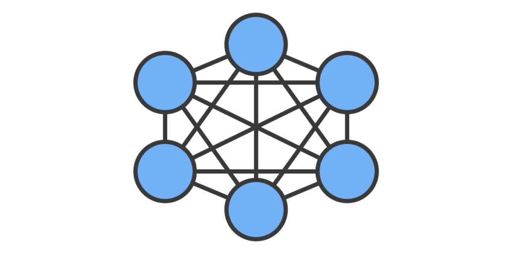
In a fully connected network, every node in the network is connected to every other node in the network. This is the most fault tolerant topology as any failure in the network will not effect any other connection. The draw back with a fully connected network is that the number of links grows quadratically with the number of nodes. For example, a network of 10 nodes would require 45 links, but a network of 20 nodes requires a total of 190 links. This makes fully connected networks impractical and expensive for larger networks.
Hybrid
Most networks today use some form of hybrid network topology. A Hybrid network uses multiple topologies together to create larger networks.
That covers the basics of network topologies. We will look at more complex networks in future as we continue to look at networking.
If you haven’t already, consider joining our newsletter to stay up to date with all the latest in Show Control, we have a daily and weekly option so you can be on the bleeding edge, or a little more reserved.